




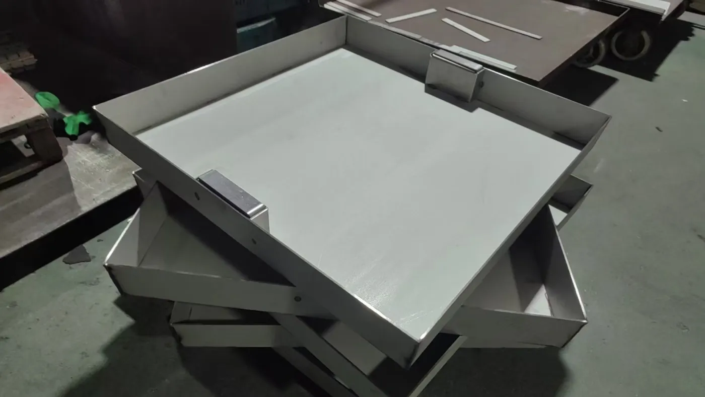
Large utility chambers create a practical design problem: a single access cover may become too wide, too heavy or too difficult to remove safely. A multi-leaf access cover solves this by dividing the opening into several coordinated panels supported by a perimeter frame and, when necessary, removable intermediate beams.
The concept is simple, but a reliable specification requires more than an overall length and width. The designer must consider how each leaf will be lifted, which parts must be removable, how the frame transfers load, what floor finish will fill the trays and how maintenance teams will use the opening after installation.
What Is a Multi-Leaf Access Cover?
A multi-leaf access cover is a framed system containing two or more removable or hinged cover sections. The leaves share one structural opening and are typically arranged across removable or fixed supports. When only routine inspection is needed, one leaf can be opened. When equipment must pass through the chamber, all leaves and specified crossbars can be removed.
This format is commonly used over mechanical rooms, pump chambers, cable vaults, treatment equipment, basement services and large underfloor utility spaces. Stainless steel is selected where corrosion resistance, hygiene or architectural appearance matters.
Start With the Required Clear Opening
Do not specify only the visible cover size. State the structural opening and the clear access required after covers and removable beams are taken out. These are not always the same. A frame may reduce the usable opening, while a fixed crossbar can prevent large equipment from passing through.
An installation section should show the slab edge, frame support, finished floor level, waterproofing or drainage layer and available installation depth. If the chamber already exists, record diagonal measurements and corner conditions rather than assuming it is perfectly square.
How to Decide the Number of Leaves
The best leaf arrangement balances handling, structural performance and access. A small number of wide leaves reduces joints but increases individual weight. More leaves are easier to handle but add interfaces, locking points and installation steps.
Ask who will open the cover and what equipment will be available. A tray filled with stone or concrete can weigh much more than the stainless steel fabrication alone. The anticipated infill weight must therefore be included when deciding leaf dimensions and whether lifting assistance is needed.
Removable Beams and Support Strategy
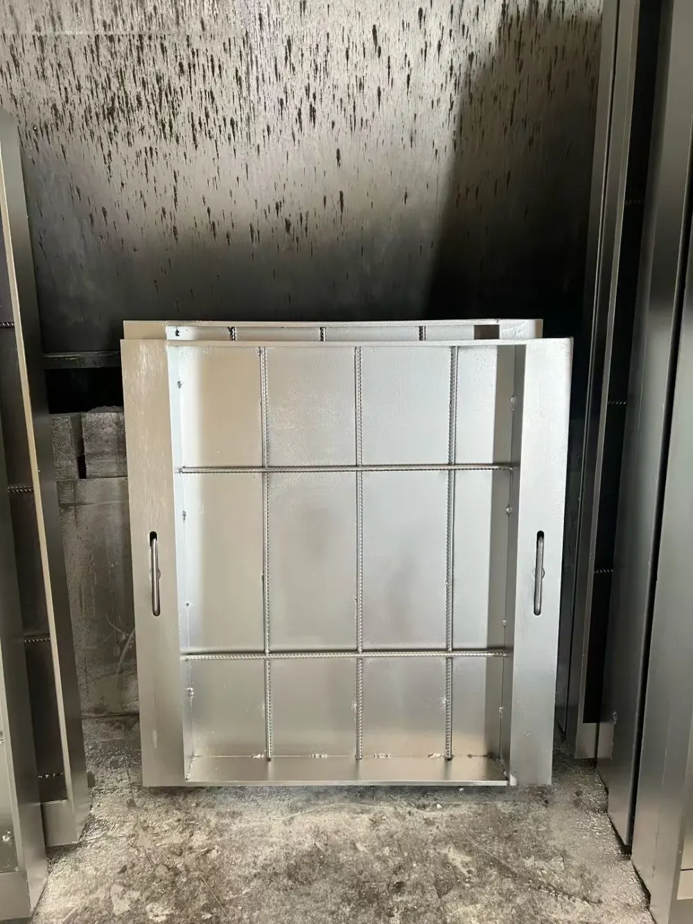
Intermediate beams shorten the unsupported span of each leaf and help distribute load to the frame. Where full chamber access is required, these beams can be designed for removal after the leaves are lifted. Their sequence, locking method and bearing points should be clear on both production and installation drawings.
Every removable part should have a defined orientation. Numbered leaves and beams reduce confusion during site assembly and future maintenance. For large systems, a simple lifting and removal diagram can be as valuable as the fabrication drawing.
Load Requirements Must Be Project-Specific
Terms such as pedestrian duty or heavy duty are not enough for engineering approval. State the required design load or applicable load class, the loaded area, support condition and expected traffic. A pedestrian floor, a pallet trolley route and a vehicle-access yard create very different demands.
The load review affects tray depth, plate thickness, stiffener spacing, beam size and frame anchorage. It may also affect allowable deflection, because excessive movement can crack tile or stone even when the metal structure does not fail.
| Specification Item | Why It Matters |
|---|---|
| Structural opening | Defines the frame and usable access area |
| Required clear opening | Determines whether crossbars must be removable |
| Traffic and design load | Controls plate, stiffener and support dimensions |
| Infill material and depth | Affects tray weight and finished floor level |
| Opening frequency | Influences lifting tools, hinges and assistance options |
| Sealing requirement | Defines gasket, drainage and locking details |
Infill Depth and Finished Floor Coordination
Recessed trays may receive tile, natural stone, concrete, screed or another finish. The tray depth should match the complete build-up, including adhesive and bedding layers, not just the nominal tile thickness. The designer should also define joint width, edge treatment and whether the finished pattern must continue across several leaves.
For exposed stainless steel covers, specify plate texture and visible finish. Brushed surfaces require an agreed grain direction so adjacent leaves look consistent after installation.
Sealing, Drainage and Odour Control
A multi-leaf system contains more joints than a single cover, so sealing needs careful definition. If the project requires control of surface water, odour or process vapour, state the exposure condition and acceptance test. A gasket alone does not automatically establish a watertight or gastight rating.
Consider where incidental water will go. Some installations need a drainage channel around the frame, while others rely on a raised curb or protected interior location. Locking points must provide adequate and reasonably uniform gasket compression.
304 vs 316 Stainless Steel
Grade 304 is widely used for indoor architectural and commercial applications. Grade 316 is often considered for coastal, pool, chemical-cleaning or chloride-exposed environments. The correct choice depends on exposure, cleaning practice and maintenance expectations rather than appearance alone.
Specify whether all structural parts, fasteners, lifting hardware and removable beams must use the same grade. Mixed material requirements should be identified before quotation.
Manufacturing and Quality Checks
A matched multi-leaf system should be trial assembled during production. Useful checks include frame squareness, leaf clearances, removable-beam fit, lifting-point operation, weld condition, tray flatness and identification marks. Material certificates and dimensional inspection records can be supplied when requested.
Because site openings can vary, approved drawings should distinguish manufacturing dimensions from minimum clearances. Learn more about AODSON’s quality control and material traceability.
Common Specification Mistakes
- Providing only the outside cover dimension instead of the structural and clear openings
- Ignoring the final weight of tile, stone or concrete infill
- Using a vague load description without a standard or design value
- Making crossbars fixed when full equipment access is required
- Requesting watertightness without defining exposure or a test method
- Leaving finished floor depth and edge joints unresolved
RFQ Checklist for Multi-Leaf Access Covers
For an accurate quotation, provide a plan and section drawing, structural opening, required clear opening, finished floor build-up, material grade, design load, sealing expectation, leaf preference, opening frequency, quantity and installation location. Include the largest item that must pass through the opening.
Review AODSON’s large-format multi-leaf stainless steel access covers or send your drawings for a manufacturability review.
Frequently Asked Questions
How large can a multi-leaf access cover be?
There is no useful universal maximum. Size depends on support conditions, leaf handling, transport, load and the removable-beam arrangement. The complete opening should be reviewed as a system.
Should the beams be removable?
They should be removable when the project needs unobstructed access for equipment. For inspection-only openings, fixed supports may be acceptable.
Can the cover be tiled to match the floor?
Yes. The tray depth and reinforcement must account for the tile, adhesive or bedding layer and the added lifting weight.
What information has the greatest effect on price?
Opening size, number of leaves, stainless grade, design load, tray depth, removable beams, locking and sealing details are the main cost drivers.