




A machine leveling foot is a small component in a large load path. Its threaded stem, base, pad and frame connection must work together to support the equipment at the required height. Selecting a foot from thread diameter alone misses the effects of uneven load sharing, stem extension, floor pressure and lateral forces.
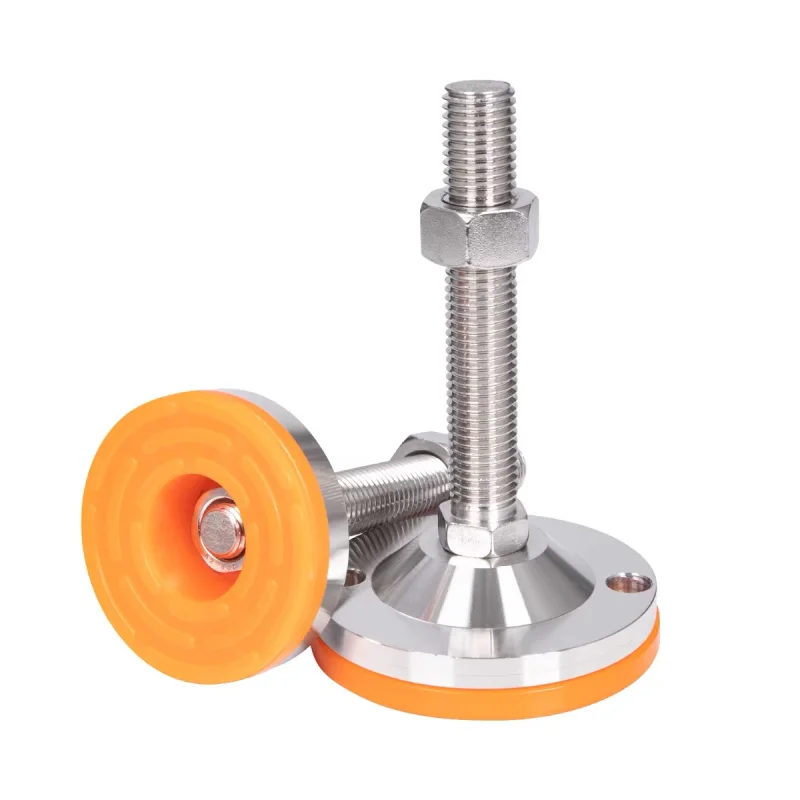
This guide uses the recently published AODSON stainless steel adjustable leveling feet as photographic examples. The images show actual product configurations; the numerical examples below are engineering illustrations, not load ratings for those products.
1. Calculate the load at each support
Begin with the complete operating mass: machine structure, tooling, product, fluids and attachments. For a perfectly centered load on equally loaded supports, an initial estimate is F = mg / n, where m is mass in kilograms, g is approximately 9.81 m/s² and n is the number of supports. The result is force in newtons, not kilograms.
For an illustrative 800 kg machine on four equally loaded feet, the estimate is 800 × 9.81 / 4 = 1,962 N per foot. This is only the symmetric static case. An offset motor, changing workpiece position, conveyor tension or floor irregularity can increase the reaction at an individual foot.
Four supports do not automatically share load equally. Frame stiffness and adjustment determine which feet actually carry the load. Obtain support reactions from the equipment design where possible, and select against the highest credible reaction rather than the average. Agree any dynamic allowance and design factor with the equipment engineer; a universal multiplier cannot cover every machine.
2. Specify stem extension as well as thread size
A specification such as “M16 leveling foot” leaves several important dimensions open: pitch, stem length, unsupported length, minimum thread engagement and adjustment travel. At the same thread size, a tall installation can behave differently from a short one.
A lateral force acting at a distance from the support produces bending. Longer exposed stems also need a stability assessment under compression. Manufacturer guidance from JW Winco distinguishes purely vertical static loading from bending or angular loading, which can reduce allowable capacity. This principle should inform the review of any leveling assembly.
On the approved drawing, show the highest and lowest operating positions and the mating frame insert. Confirm that sufficient thread remains engaged at maximum extension and that the stem does not bottom out at minimum height. The lock nut must bear against a suitable frame surface without substituting for adequate thread engagement.
3. Match base area to the actual floor interface
A preliminary average contact-pressure calculation is p = F / A. For a fully contacting circular base, A = πD² / 4. With an illustrative 2,000 N force, an 80 mm diameter footprint gives about 5,027 mm² and an average pressure of 0.398 MPa. A 50 mm footprint gives about 1,963 mm² and 1.02 MPa.
These calculations compare ideal footprints, not finished-foot capacities. Holes, pad recesses, raised rings, floor unevenness and pad deformation can reduce the effective contact area or concentrate pressure. Review the complete floor build-up, including coatings or tiles and their substrate, rather than checking concrete alone.
4. Decide whether the base needs articulation or fixing holes
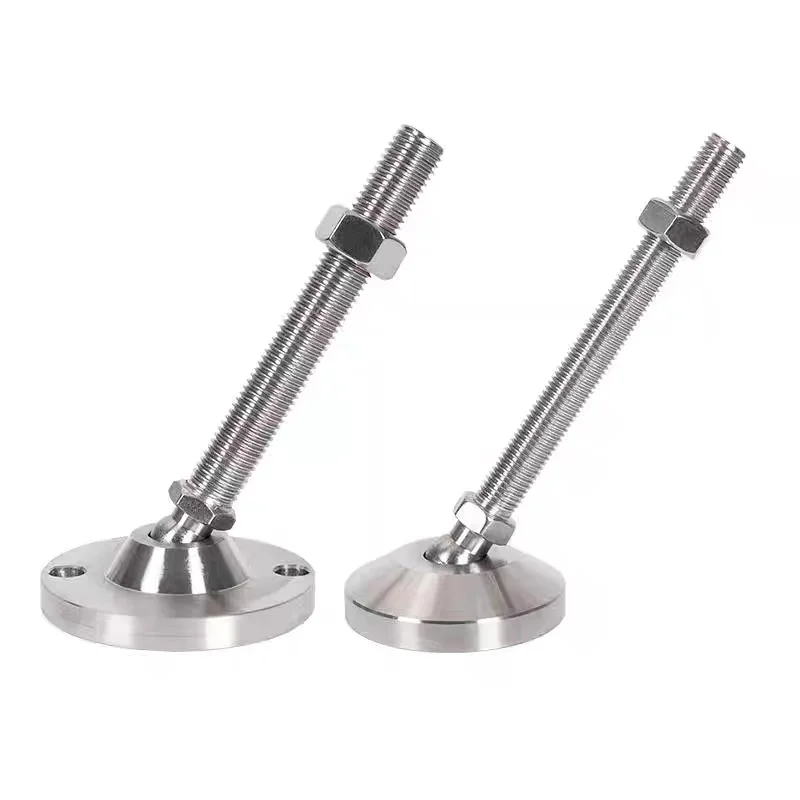
An articulating joint can accommodate a defined angular mismatch between the stem and floor. It is useful only within the joint’s specified range and loading conditions. Request the joint detail, permissible angle and capacity at the selected installation position.
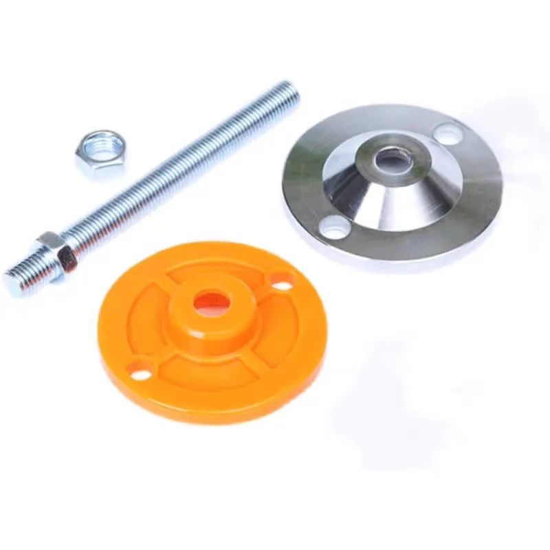
Fixing holes introduce a different requirement: the equipment can be restrained through a flange and floor fasteners. The foot flange, anchor, floor substrate and equipment frame must all be assessed for the intended forces. Hole presence does not establish an anchor rating.
| Design question | Information to confirm | Why it matters |
|---|---|---|
| How much adjustment is required? | Operating height, travel and maximum exposed stem | Defines geometry at the most demanding position |
| Is the floor sloped? | Required articulation and local floor condition | Avoids unintended edge contact and stem bending |
| Must the equipment be restrained? | Fixing pattern, lateral forces and anchor design | Connects foot selection to the floor attachment |
| Can the floor tolerate the footprint? | Effective area and floor pressure limit | Reduces coating or substrate damage risk |
5. Treat the pad as a specified component
Black or orange color does not identify an elastomer or its properties. Specify compound, hardness, thickness, temperature range, chemical exposure and retention method. Sustained compression can change pad thickness and equipment height; request relevant compression or creep information for the operating conditions.
A floor-protection pad is not automatically a vibration isolator. For a simplified single-degree-of-freedom model, natural frequency is fₙ = (1 / 2π) √(k / m). Here k is the equivalent support stiffness and m is supported mass. A real isolation assessment also requires damping, excitation frequency, load distribution and the pad’s stiffness at working load. Pad color and nominal thickness cannot supply those inputs.
6. Define material and inspection requirements
The product reference lists 304 stainless steel as an option. Confirm the ordered metal grade for the stem, base and nuts, as well as the required finish. Specify the actual washdown liquid, cleaning chemicals, temperature and exposure duration when material compatibility matters.
Inspection should connect to the drawing: thread fit, stem straightness, base dimensions, hole position, articulation and pad retention. If load testing is required, define loading direction, stem extension, dwell time, acceptance criteria and sampling. A test performed in a short, vertically loaded configuration does not validate every installed condition.
Installation and quotation checklist
Send the maximum reaction per support, equipment drawing, thread and pitch, adjustment range, frame engagement, base dimensions, pad specification and fixing layout. Include operating motion, floor construction, environmental exposure and the inspection scope.
During installation, level the equipment using the manufacturer’s procedure, confirm all intended supports carry load and secure the locking hardware as specified. Recheck height and stability after commissioning or changes in operating load.
Review the leveling-foot product photographs, then send your drawing and support requirements for component review. The final selection depends on the complete equipment installation, not appearance alone.