




Wedge wire filter nozzles perform two connected jobs: retaining treatment media and providing a flow path through a filter’s distribution or collection system. A slot opening that retains media can still produce an unsuitable assembly if open area, stem restriction, nozzle spacing or backwash duty is overlooked.
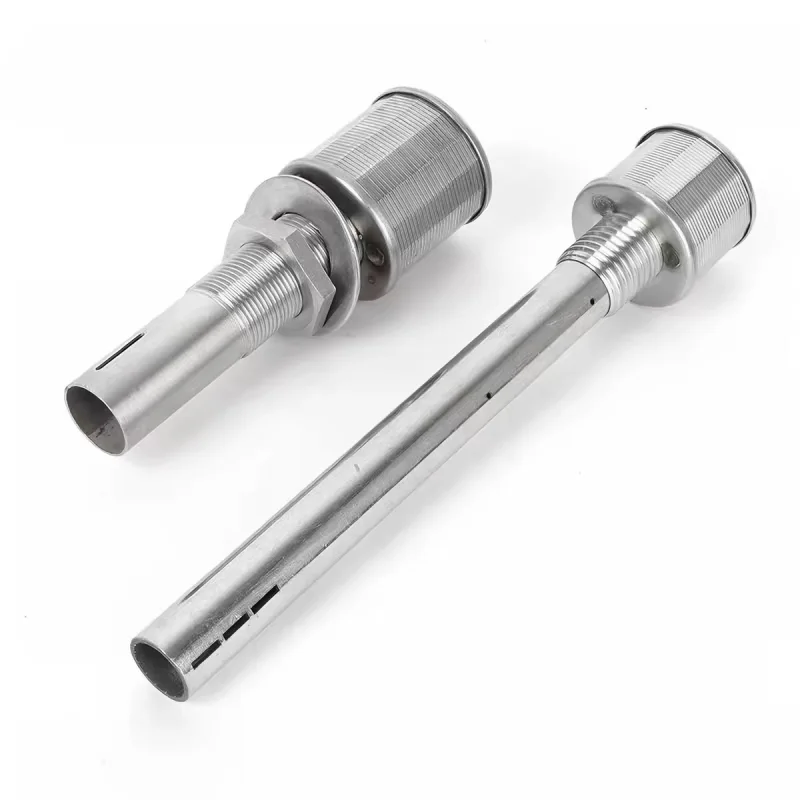
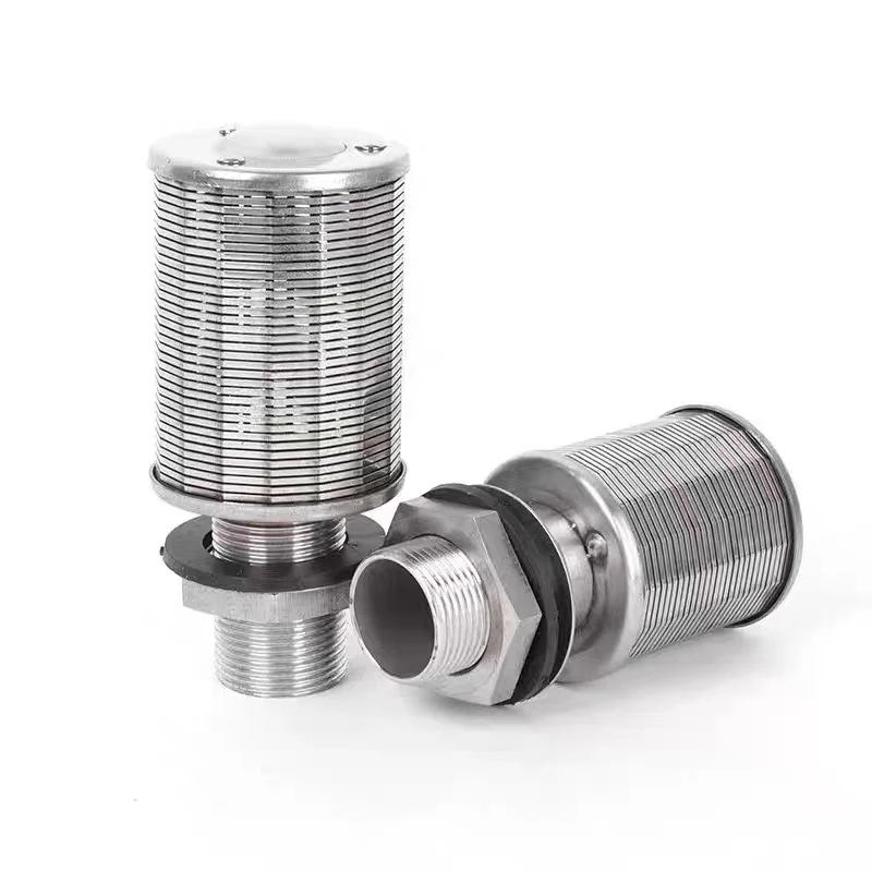
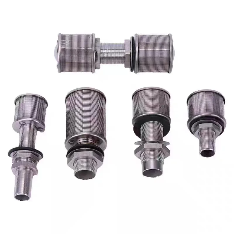
This technical guide uses the recently published AODSON stainless steel wedge wire filter nozzles as real photographic examples. Slot tolerances, hydraulic curves and pressure limits must come from the approved component specification; they cannot be measured reliably from a product photograph.
1. Separate media retention from filtration rating
In a media-filled vessel, the bed performs much of the treatment while the nozzle retains the bed material and collects or distributes fluid. Nozzle slot size is therefore not automatically the filter system’s particle-removal rating.
Request the media particle-size distribution, including fines, and information about particle shape, wear and handling. The media supplier or process designer should define the retention requirement. A nominal media size alone can hide smaller particles capable of passing through a slot.
Specify both nominal opening and permitted variation. If the design depends on a maximum opening, that limit must be controlled across the relevant screen length, including weld and end regions. Define how openings will be measured and what constitutes a reject. A single acceptable measurement is insufficient evidence of a uniform screen.
2. Calculate a geometric open-area estimate
For an ideal repeating slot-and-wire surface, an approximate open fraction is φ = s / (s + w), where s is slot width and w is the projected wire-face width. Both dimensions must use the same units.
For an illustrative 0.20 mm slot and 1.00 mm wire face, φ = 0.20 / 1.20 = 16.7%. With the same slot and a 0.75 mm wire face, the estimate becomes 21.1%. Changing wire geometry alters open area without changing the nominal retention opening.
This simplified expression excludes blocked regions, supports, end caps and the details of a curved welded assembly. Use the drawing or measured net open area for hydraulic work. Increasing open area may also change wire strength, support requirements or fabrication limits, so opening percentage cannot be optimized independently.
3. Check flow through the entire nozzle
For a first estimate, average velocity through net screen area is v = Q / Aopen. With an illustrative 0.30 m³/h per nozzle, Q is 0.0000833 m³/s. If net screen opening area is 1,200 mm², or 0.0012 m², average slot velocity is about 0.069 m/s.
That value does not predict pressure drop by itself. The screen entrance, internal head, stem bore, stem slots and exit each contribute resistance. Obtain a flow-versus-pressure-drop curve for the complete nozzle at the applicable fluid properties and flow direction.
The Johnson Screens industrial brochure treats nozzle design and quantity as application-dependent and reports collection and backwash flows separately for its own products. That distinction is useful during specification, but those catalog values are not ratings for the AODSON examples pictured here.
4. Do not assume identical nozzles ensure uniform distribution
Dividing total flow by nozzle count gives an average design flow, not proof of uniform operation. Different manifold distances, local bed conditions, assembly elevations or blocked openings can produce different branch resistances.
In a simplified network with identical branches and equal driving pressure, equal flow is plausible. In an actual vessel, assess the distribution plate or manifold together with the nozzle resistance and bed pressure drop. Increasing nozzle resistance may improve flow balancing but also consume pump head; the acceptable balance is a system-design decision.
Provide the vessel diameter, nozzle arrangement, manifold layout, operating flow range and required uniformity. Specify the installation elevations and available clearances. A replacement nozzle should preserve the approved hydraulic behavior as well as physically fit the hole.
5. Evaluate filtration and backwash as separate cases
Backwash can reverse flow and introduce different loads from normal operation. Liquid-only duty, air scour and combined air-water operation must be defined separately. Describe sequence, flow rate, temperature and any transient conditions rather than listing one nominal flow.
Request differential-pressure limits across the screen in each required direction. Vessel operating pressure and nozzle differential pressure are different quantities: a high-pressure vessel can have a small normal screen differential, while a blocked nozzle may experience a larger local differential.
Where extended stems or air-distribution openings are required, confirm their geometry and position relative to the mounting plate. Assembly height can affect access, flow passages and the intended air-water arrangement. Do not substitute a short-stem design solely because the thread matches.
6. Define the mounting and sealing interface
| Interface | Drawing requirement | Acceptance concern |
|---|---|---|
| Thread | Standard, size, pitch, gender and engagement | Fit, installation clearance and unintended leakage |
| Mounting plate | Thickness, hole size and seat geometry | Correct nut position and assembly height |
| Seal | Compound, dimensions and compression method | Fluid compatibility and bypass around the screen |
| Stem | Bore, openings, length and orientation | Hydraulic restriction and interference |
| Screen | Slot limits, wire profile and net open area | Media retention and flow performance |
A bypass path around the mounting seat can release media even when every screen slot meets specification. Inspect the plate and sealing interface as part of the assembly. Define tightening instructions and any locking provision with the equipment supplier.
7. Specify materials, inspection and maintenance
The product reference lists 304 and 316L stainless steel options. Selection requires the actual fluid chemistry, temperature, cleaning regime and exposure conditions. Define materials for the screen, stem, welds and sealing components rather than specifying only the visible head.
A useful inspection plan checks slot distribution, weld condition, head dimensions, thread fit, stem openings and assembly height. If flow or differential-pressure testing is required, state the test fluid, temperature, flow direction, measurement locations and acceptance criteria. Agree whether qualification applies to a design or to each production batch.
For operation, record clean-system pressure drop as a baseline under defined conditions. Investigate changes alongside bed condition and flow rate; a pressure change alone does not identify nozzle fouling. Confirm access, removal clearance, spare parts and a cleaning method compatible with both metal and seals.
Prepare a complete nozzle RFQ
Send media data, retention criteria, normal flow, backwash sequence, nozzle count and layout, allowed pressure drop, differential-pressure limits, fluid conditions, mounting drawing and material requirements. Add the inspection scope and required documentation.
Browse the actual filter-nozzle configurations and submit your equipment drawing and process duty. Review the quality-control information when agreeing measurements and acceptance criteria.