




A stainless steel drain grate can look substantial yet behave poorly if its bearing bars run in the wrong direction or its frame does not transfer load into the surrounding structure. For procurement, the useful question is not simply “How thick is the grate?” It is “What load travels across which unsupported span, into which supports?”
This guide focuses on the structural and installation details behind stainless steel bar grating drain covers. The real product photographs illustrate construction options, not certified load classes. Load capacity, accessibility and slip performance must be verified for the exact supplied panel and installation.
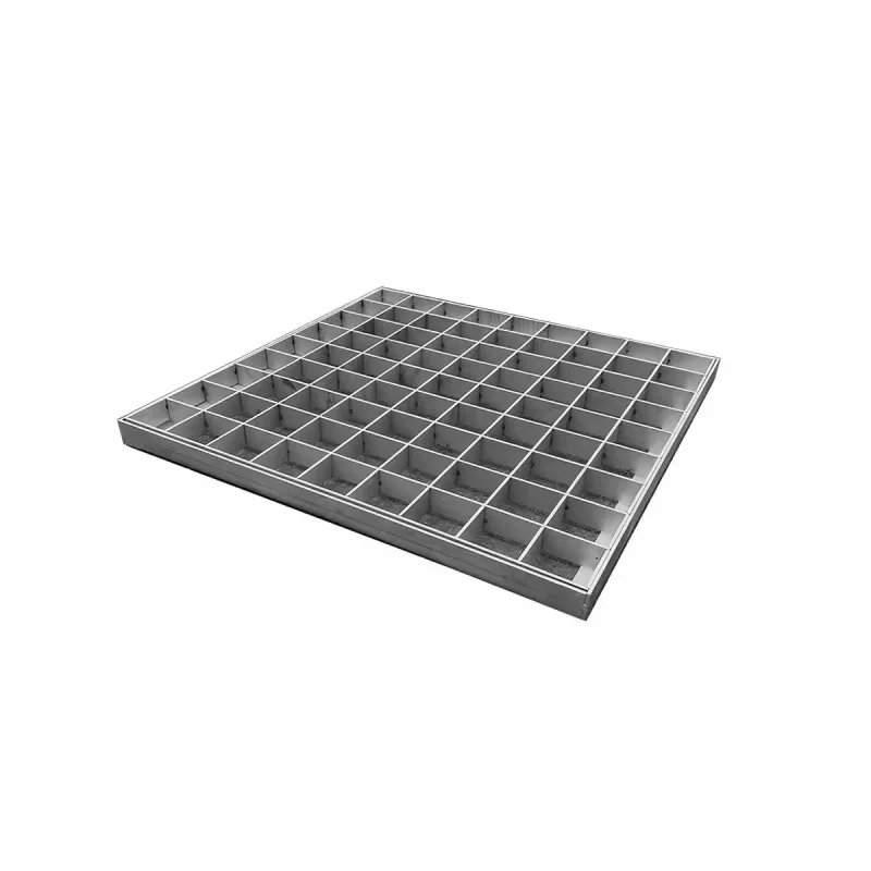
1. Start with the load path and bearing-bar direction
Identify the principal bearing bars on the fabrication drawing. These are the members intended to span between supports; cross bars connect the assembly but should not automatically be treated as equivalent load-carrying beams. Show the bearing direction with an arrow and mark the supporting edges.
Separate overall panel length, panel width, opening size, seat width and clear unsupported span. A 400 mm external dimension may include a surrounding frame and overlap. Conversely, a small panel can still be unsuitable if the actual supports are missing or poorly seated. The supplier needs the support geometry, not just a photograph and an outside dimension.
For a rectangular trench, confirm which edges actually provide continuous seating. Do not rotate a panel during installation just because it fits the opening. That can change the effective span or leave the intended bearing bars without their specified support.
2. Why span can matter more than appearance
A simplified beam model makes the sensitivity clear. For a simply supported member carrying a uniform line load w, the maximum elastic deflection is δ = 5wL⁴/(384EI). L is span, E is elastic modulus and I is second moment of area. For a rectangular bar standing on edge, I = th³/12, with thickness t and vertical depth h.
Keeping the same section and uniform line load, doubling span increases calculated deflection sixteenfold. Keeping thickness and span unchanged while doubling bar depth increases I eightfold. These comparisons explain why a wide unsupported opening or a shallow bar can dominate behavior even when the grate has many intersections.
The model is educational, not a load table for a photographed product. Actual load sharing, weld details, end restraint, material condition, concentrated loads and frame behavior need analysis or testing. Also note that the sixteenfold comparison assumes the same line load, not the same total load: changing that assumption changes the result.
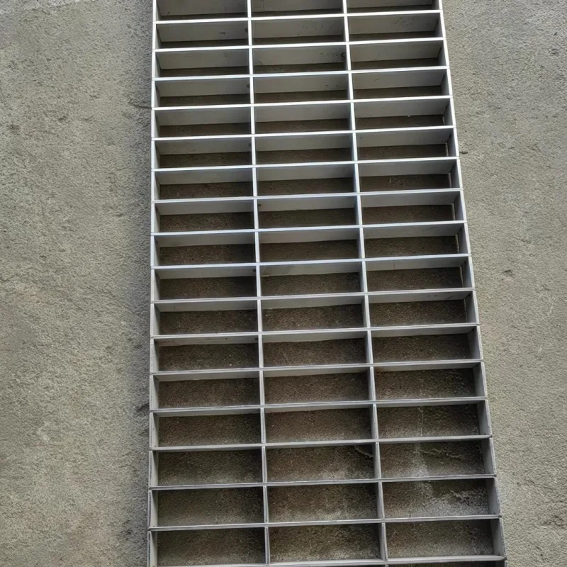
3. A wheel load is not a pedestrian distributed load
List anticipated users and equipment: pedestrians, trolleys, carts, maintenance equipment or vehicles. A narrow wheel contact can concentrate force onto a small group of bars. The wheel footprint, location relative to the supports and direction of travel matter, as do impact and braking or turning forces.
Ask for documentation that matches the intended load case and span. A distributed-load statement cannot automatically substantiate a concentrated wheel load. “Heavy duty” is a description, not a test certificate. If a project requires a named drainage-cover standard or load class, specify that requirement and obtain evidence for the complete cover-and-frame assembly before acceptance.
Do not select a panel from total vehicle mass alone: wheel loads and their distribution are the relevant starting point. Likewise, support calculations cannot stop at the removable panel. The frame, anchors, concrete or other supporting substrate must carry the transferred forces.
4. Design the frame to seat, locate and restrain the cover
A useful frame detail shows continuous seat geometry, installation level, specified panel clearance, anchorage and the surrounding construction. Poorly aligned seats can cause rocking even if the panel itself is stiff. An excessive height difference creates a trip edge; too little clearance can make maintenance removal difficult.
Decide whether the cover needs hold-downs or other restraint against movement and unauthorized removal. Drain cleaning still needs a practical lifting method and safe access. Do not cut bearing bars or enlarge openings on site without an approved revised design.
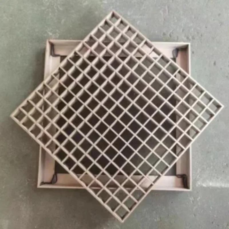
5. Separate clear openings, drainage area and accessibility
Pitch is a centre-to-centre spacing; clear opening is the gap between bars. They are not interchangeable. For an ideal orthogonal grid with uniform projected bar thicknesses t₁ and t₂ and pitches p₁ and p₂, a first estimate of open-area fraction is [(p₁ − t₁)/p₁] × [(p₂ − t₂)/p₂]. This assumes rectangular unobstructed openings and excludes border frames and other obstructions.
For example, equal 25 mm pitches and 3 mm projected thicknesses give approximately 77% theoretical open area. That number is not a drain-flow rating. Rainfall intensity, inlet approach flow, debris, blockage allowance, channel slope and outlet capacity can govern performance. A hydraulic check must consider the whole drainage system.
Accessibility is a separate project constraint. For covered US applications, the US Access Board’s ADA Standards, section 302.3, generally restrict floor openings to those that do not pass a sphere larger than 1/2 inch (13 mm), with stated exceptions; elongated openings must be oriented across the dominant travel direction. Confirm applicability with the project designer. This is not a universal global rule, a heel-proof claim or evidence of slip resistance.
6. The enquiry checklist that avoids redesign
- Dimensioned opening and frame drawings, including clear span and bearing direction.
- Material specification, bar depth and thickness, pitches and clear gaps.
- Actual concentrated and distributed loads, wheel footprints and required verification standard.
- Seat, anchor and supporting-substrate details; installation height and removal method.
- Drainage duty, debris conditions, cleaning frequency and access requirements.
- Surface finish, environment, accessibility and slip-performance requirements.
Use the AODSON drain grating product page to discuss construction and dimensions, and include the support drawing in your enquiry. For pedestrian opening design, also see our heel-proof drain grate specification guide. Evaluate opening geometry and structural performance together, rather than treating either as a substitute for the other.
Frequently asked questions
Does stainless steel thickness determine load capacity?
No. Bearing-bar depth and thickness, unsupported span, load position, connections and frame support all contribute.
Does high open area guarantee better drainage?
No. Blockage, approach flow and the downstream channel or outlet can still limit capacity.
Can a grate be called vehicle-rated from a product photo?
No. Obtain applicable assembly-specific test or engineering documentation for the required load case, support arrangement and market.