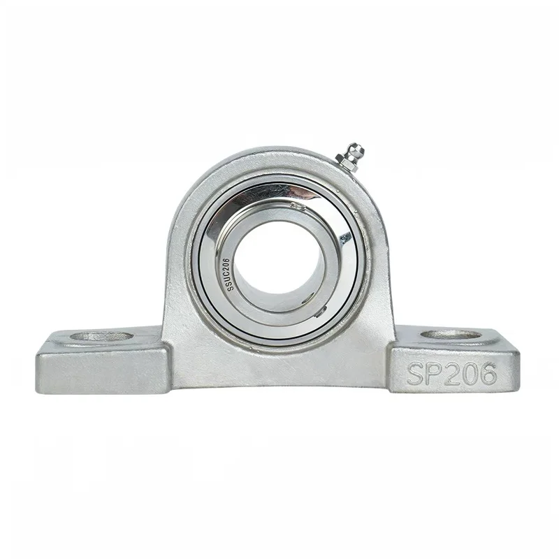
The bearing insert is often the first item engineers compare, but the housing decides how the shaft is supported by the machine. A pillow block and a flange unit can use a similar insert and still create very different load paths, alignment constraints and maintenance access.
The correct choice begins with the mounting plane. A pillow block sits on a base parallel to the shaft. A flange unit bolts to a wall or plate perpendicular to the shaft. That simple geometry affects almost every later decision.
Quick selection rule
- Choose a pillow block when the shaft runs above a base or frame and the bearing can be supported from below.
- Choose a flange unit when the shaft passes through a vertical plate, machine wall or end frame.
- Choose a piloted flange when accurate housing location should come from a machined register rather than bolt clearance.
- Choose a take-up unit when bearing position must move to tension a belt or chain.
These are layout rules, not load ratings. Capacity must be checked from the bearing series, shaft fit, speed, lubrication, housing and actual load direction.
Mounting geometry and structural stiffness
A pillow block transfers load into its feet and base bolts. The support plate must be flat and stiff enough to avoid twisting the housing when bolts are tightened. If shims are needed, they should support the full footprint rather than create a local high point.
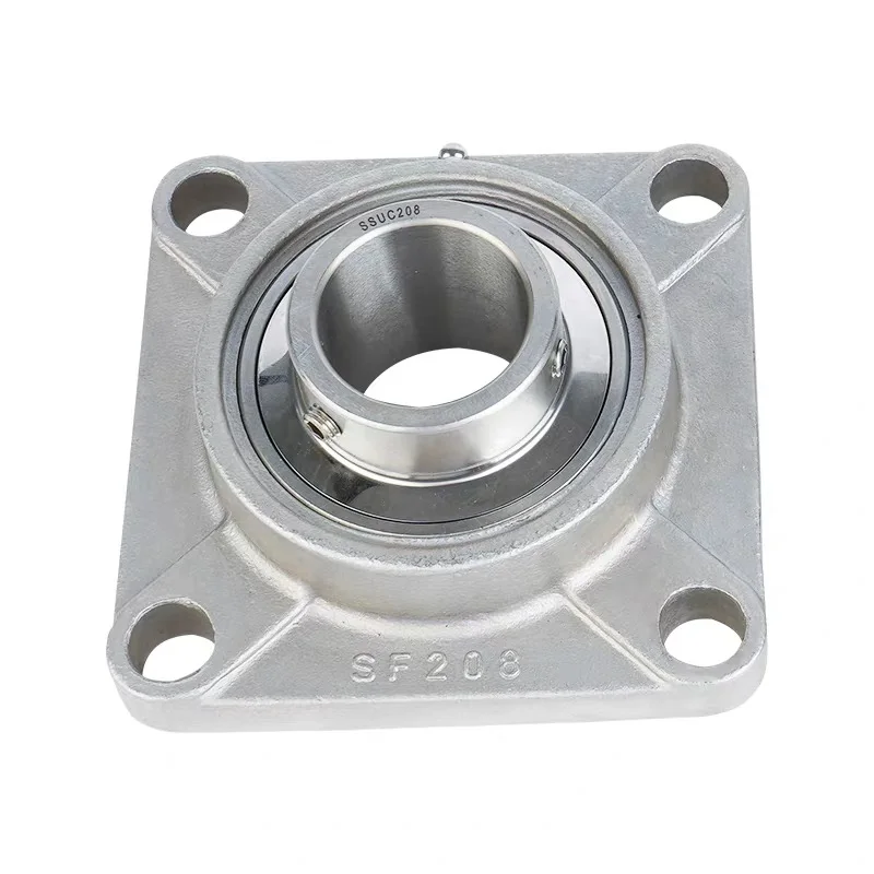
A flange housing transfers load into a face plate. The plate must resist bending and provide clearance for the shaft, seals and fasteners. A thin wall can deflect even when the bearing itself is correctly sized. Square four-bolt flanges spread the connection over a wider pattern; two-bolt oval flanges fit tighter envelopes but give the structure a different moment arm.
SKF’s mounting instructions tell installers to clean the shaft and support surfaces, verify shaft diameter, ensure the support is flat and bolt either pillow-block or flange housings securely. Those basic steps matter because a precision bearing cannot compensate for a distorted mounting surface. See the SKF mounting instructions.
Load direction and bearing life
Do not infer allowable load from the number of housing bolts. Calculate the radial and axial bearing loads, duty cycle, shock factor, speed and required life. Then check the insert bearing’s dynamic and static ratings, the housing strength, bolt capacity and supporting structure.
A heavily overhung pulley can generate a large bending moment even when belt tension appears moderate. A flange unit on a flexible plate may suffer misalignment from plate deflection. A pillow block on a rigid base may be better—or the shaft layout may need two bearings placed farther apart. Housing style is only one part of the system.
Alignment: accommodation is not permission for poor installation
Many mounted inserts have a spherical outside surface that permits initial misalignment within the housing. This helps installation, but it does not make a crooked shaft line harmless. Misalignment can raise seal friction, alter internal load distribution and shorten grease life.
SKF’s maintenance handbook distinguishes pillow, flange and take-up mounting steps and emphasizes careful alignment. It notes that permissible misalignment depends on operating and relubrication conditions; always use the limit for the exact bearing series rather than a generic number.
Shaft locking method
Common options include set screws, eccentric locking collars, adapter sleeves and interference fits. Each has different requirements for shaft tolerance, direction of rotation, axial holding and removal.
- Set screws: simple and compact, but tightening sequence and shaft hardness matter.
- Eccentric collar: locked in the direction of rotation and secured with a set screw.
- Adapter sleeve: useful for tapered-bore bearings and controlled internal clearance.
- Press fit: may be required at high load, but needs defined tolerances and assembly tooling.
Specify shaft diameter and tolerance, not only nominal bore. A loose fit can fret; an excessive interference can reduce internal clearance.
Seals, lubrication and stainless construction
Stainless housings are useful in washdown, food equipment, outdoor machinery and corrosive environments, but the complete unit must be reviewed. The insert rings, balls, cage, grease fitting, fasteners, seals and lubricant may not all be the same material.
Choose seals for the real contamination: water spray, fine dust, fibers, chemicals or abrasive particles. More sealing contact usually creates more friction and heat. Lubrication interval depends on speed, temperature, load and contamination; the presence of a grease fitting does not define the interval.
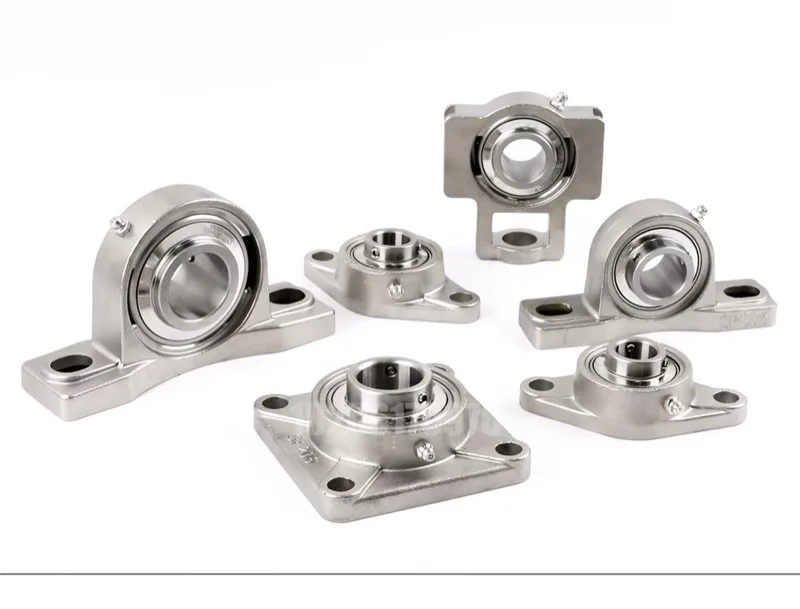
SKF identifies standard housing families including pillow block, square flange, oval flange, round flange and take-up units. Timken’s housed-unit guidance also distinguishes fixed and expansion arrangements. On longer shafts, one bearing location commonly controls axial position while another allows thermal growth. Do not lock both ends axially without checking expansion.
Comparison table
| Question | Pillow block | Flange unit |
|---|---|---|
| Mounting plane | Base parallel to shaft | Face perpendicular to shaft |
| Typical structure | Frame rail, skid, machine base | Side plate, wall, end frame |
| Alignment adjustment | Often easier to shim at base | Often governed by face flatness/register |
| Envelope | Requires height above base | Requires area around shaft opening |
| Service access | Good from above and sides | Depends on rear-side access |
What to specify on an RFQ
- shaft diameter, tolerance and surface condition;
- radial and axial loads, speed and duty cycle;
- mounting orientation and available bolt pattern;
- fixed or expansion bearing location;
- locking method, seal type and lubrication plan;
- temperature, washdown chemicals and contamination;
- housing and insert materials;
- required certificates, quantity and dimensional drawing.
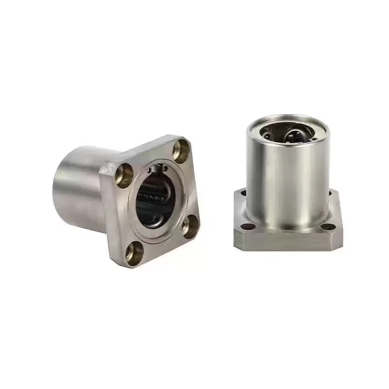
Compare AODSON’s real stainless steel pillow block unit, four-bolt square flange units, square flange linear bearings and compact mounted bearing units. For a project-specific size or material, send the shaft and mounting data through the request form.