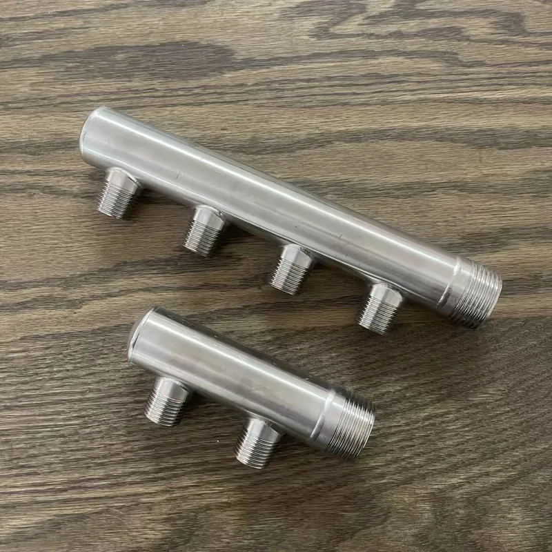
A water distribution manifold can be beautifully welded, perfectly polished and still perform badly if the header is sized from the thread label alone. The job is not simply to choose a one-inch inlet because there are four half-inch outlets. The useful question is: what flow must reach each branch, at the same time, with how much pressure left at the most demanding outlet?
This guide explains a practical sizing sequence for a compact threaded water manifold. It applies to fabricated tubular headers used in equipment, filtration skids, cooling circuits, irrigation assemblies and general utility water systems. It is not a substitute for a piping calculation or the project code, but it gives buyers and designers a much better RFQ than “1-inch in, four outlets.”
Quick answer: size the header from simultaneous demand
Start with the required flow at every branch and decide which branches may operate together. Add those simultaneous flows to obtain the design flow through the inlet and the first section of the header. Select a provisional internal diameter from an acceptable velocity, then calculate friction and fitting losses to the hydraulically worst branch. Finally, confirm wall thickness, thread geometry, material, weld quality and test pressure.
The outside diameter and nominal thread size are not enough. Two manifolds with the same external appearance can have different internal bores, wall thicknesses, weld penetration and pressure loss.
1. Define the operating case before choosing a pipe size
List every outlet and record its required flow and minimum inlet pressure at the connected device. Then describe the operating combinations. A five-outlet manifold does not necessarily carry five-branch flow: one system may use all five continuously, while another may select only one branch at a time.
| Input | Why it matters |
|---|---|
| Flow required at each branch | Determines branch sizing and the total inlet demand |
| Branches operating together | Prevents undersizing from simple average flow |
| Available inlet pressure | Sets the pressure-loss budget for the manifold and downstream line |
| Minimum pressure at each device | Identifies the critical or hydraulically worst branch |
| Water temperature and composition | Affects density, viscosity, material choice and seal compatibility |
| Transient operation | Fast valves and pumps can create pressure surges beyond steady-state values |
If demand is uncertain, document a normal case and a credible maximum case. Oversizing every component “just in case” can add cost and stagnant volume; undersizing creates velocity, noise and pressure loss. The target is a defensible design case.
2. Add branch flows section by section
Flow in a dead-end header decreases after each takeoff. The inlet section carries the total simultaneous demand. After the first branch removes its share, the next section carries the remaining flow, and so on. This means the highest friction and velocity are often near the inlet, but the last outlet may still be the critical point because it sees every upstream loss.
For a four-branch example, assume the design case uses three branches at 10, 7 and 5 L/min while the fourth is closed. The inlet and first header section must be checked at 22 L/min. The later sections are checked at progressively lower flow. Do not size the inlet from a single 10 L/min branch.
3. Estimate the internal diameter from flow and velocity
For incompressible flow, the relationship is:
D = √(4Q / πv)
where D is internal diameter, Q is volumetric flow and v is the selected average velocity. Use consistent units. In the 22 L/min example, a chosen design velocity of 2 m/s gives a starting internal diameter of about 15.3 mm. That is only a starting point: it must be rounded to a real tube bore and checked for pressure loss, fittings, fouling allowance and the applicable design standard.
Parker’s tube-sizing guidance makes the same engineering point from another direction: a tube that is too small raises velocity, friction loss and heat, while a tube that is unnecessarily large adds cost and packaging difficulty. Its published velocity values are application-specific guidance, not universal limits for every water manifold. Review the original Parker tube-sizing note and use the limits required by your own code and equipment.
The key detail for a fabricated manifold is the actual bore, not the nominal inlet thread. Thread roots, welded branch bosses and locally thickened ends can reduce the flow area.
4. Calculate pressure loss to the worst branch
A useful pressure-loss model includes more than the straight header:
- friction through each header section;
- loss through the inlet adapter or valve;
- run and branch losses at each takeoff;
- reducers, elbows, hoses, meters and downstream valves;
- elevation difference;
- the pressure required by the terminal device.
For detailed work, designers commonly use the Darcy-Weisbach method with a friction factor based on Reynolds number and relative roughness. Individual fittings are represented by loss coefficients or equivalent lengths. The calculation should follow the actual route to each outlet, because the last outlet is not automatically the worst one; a nearer branch feeding a restrictive device may require more pressure.
Run at least two checks: the maximum simultaneous-demand case and the minimum-flow case. The latter may reveal poor control, trapped air or stagnant sections even when maximum flow is acceptable.
5. Decide whether equal flow is actually required
A plain header distributes pressure, not guaranteed equal flow. Water tends to favor the branch with the lowest total resistance. Equal thread sizes do not produce equal branch flow when hose lengths, elevations, valves or terminal devices differ.
If close balance matters, the system may need balancing valves, calibrated orifices, pressure-compensating devices or a more symmetric feed arrangement. A center-fed or looped header can reduce pressure variation in some layouts. Those features belong in the system design; changing a polished manifold body after fabrication is an expensive way to discover the requirement.
6. Choose branch count, spacing and orientation for assembly
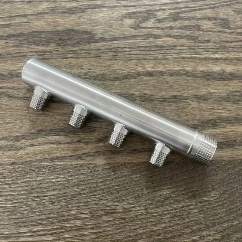
Outlet count is visible in a product photo, but spacing is often the dimension that decides whether the manifold can be installed. Leave room for the largest wrench, valve body, union nut, hose bend radius and insulation. Check whether adjacent valves can rotate without colliding.
The real stainless steel threaded water distribution manifold shown here demonstrates two-, four- and five-outlet layouts. These are configuration examples, not fixed dimensions. Branches can be placed on one side, opposing sides or at project-defined angles. A clear drawing should specify center-to-center spacing and an angular datum.
7. Treat the thread and seal as part of the hydraulic design
NPT, BSPT and BSPP are not interchangeable labels. ASME B1.20.1 covers common inch pipe threads including NPT. ISO 7-1 covers pipe threads where pressure-tight joints are made on the threads, while ISO 228-1 covers parallel pipe threads where the pressure-tight joint is not made by the threads alone.
That distinction changes the port geometry and sealing method. A BSPP connection normally needs a defined sealing face and gasket, bonded seal or O-ring arrangement. A tapered thread relies on controlled engagement plus an approved sealant. Mixing standards can seem successful for the first few turns yet damage the thread or leak in service.
8. Confirm pressure rating from the weakest feature
“Stainless steel” is not a pressure rating. The allowable working pressure depends on the material condition, temperature, tube dimensions, branch geometry, thread depth, weld design, fabrication procedure, corrosion allowance and applicable safety factor. The branch weld or threaded end may govern before the straight tube wall does.
For a custom manifold RFQ, state normal pressure, maximum operating pressure, design pressure, test pressure and any cyclic or surge condition separately. Ask the manufacturer to confirm the production and inspection route rather than copying a pressure number from a visually similar marketplace listing.
A drawing package that receives a useful quotation
- fluid and temperature range;
- normal and maximum simultaneous flow;
- inlet pressure and minimum required branch pressure;
- main and branch thread standards, sizes and gender;
- number, spacing and angular orientation of outlets;
- material grade and surface condition;
- design pressure, test method and acceptance criteria;
- mounting features and envelope restrictions;
- quantity, drawing revision and required documentation.
Read the companion guide on water manifold material and thread selection before freezing the drawing. Flow sizing and material selection interact: a corrosion allowance, coating, liner or different grade can change the practical bore and connection design.
Frequently asked questions
Can the main inlet be the same nominal size as the largest outlet?
Sometimes, but only if the simultaneous flow and pressure-loss calculation supports it. The inlet commonly carries several branch flows at once, so nominal-size matching is not a sizing method.
Will four identical ports deliver equal flow?
Not automatically. Flow division depends on the resistance of the header path, each branch line, valves and terminal equipment. Add balancing components when equal flow is a functional requirement.
Should unused future ports be included?
Future capacity can be useful, but every unused cavity adds volume and another sealed connection. Specify plugs, access and the future design flow, then check the present system at its lower operating flow.
What information is needed for a custom manifold quote?
Send the flow case, pressure and temperature, fluid, port schedule, material, dimensions, test requirement, quantity and drawing. Use the AODSON request form to attach a drawing or reference sample.