Male Threaded Locating Pins for Fixtures and Positioning Assemblies
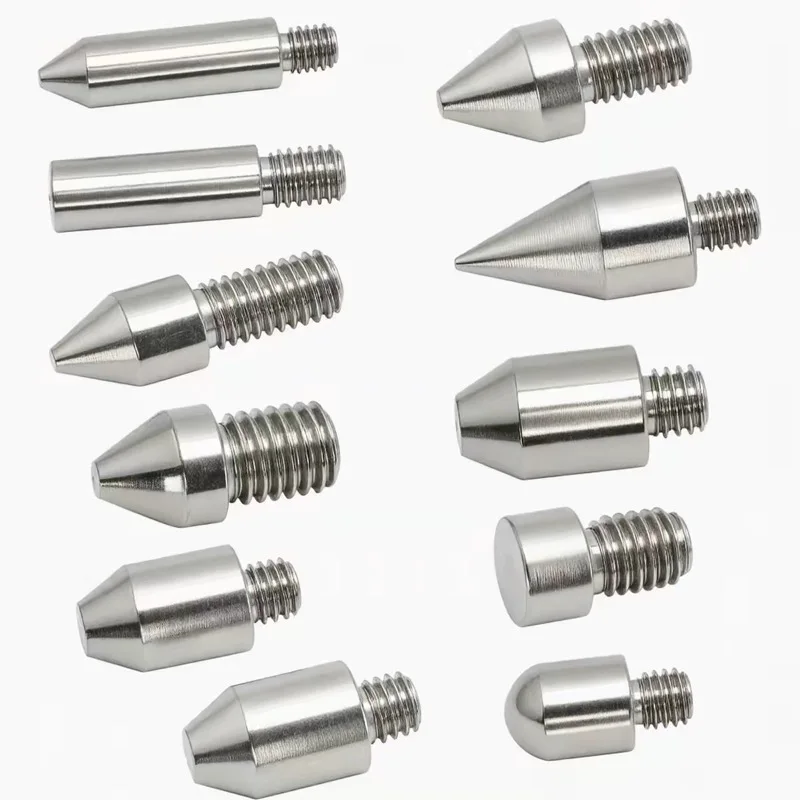
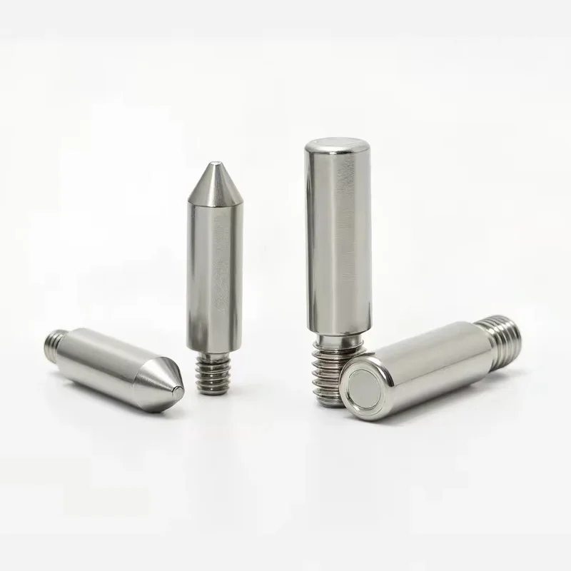
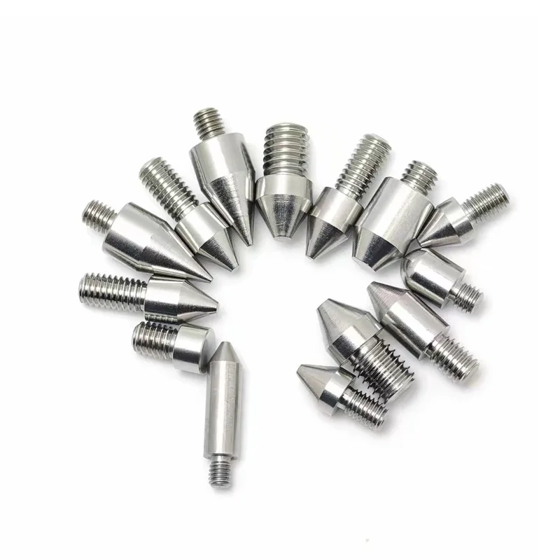
These locating pins combine an external mounting thread with a larger working body and a selected contact or lead-in profile. The supplied photographs show conical, rounded, flat and truncated ends, as well as short and extended cylindrical bodies. Choose the profile and locating dimensions to suit the receiving hole, contact surface and intended motion.
The threaded end mounts the pin into a compatible tapped component. The working diameter, shoulder and tip are separate features that need their own drawing dimensions. A matching mounting thread does not by itself establish a positioning fit or repeatability requirement.
Specifications and Ordering Options
| Item | Reference configuration / requirements to confirm |
|---|---|
| Product type | Male threaded locating pin or positioning stud with a cylindrical working body. |
| Material | Stainless steel identified in the supplied reference. Confirm the alloy standard, grade and any material records; a specific grade is not assigned from the finish. |
| Mounting thread | M3, M4, M5 and M6 listed in the reference. Confirm selected size, pitch, thread tolerance, engagement length and availability. |
| Working body | Short and extended cylindrical examples shown. Specify diameter, tolerance, body length, shoulder geometry and installed projection. |
| Tip profiles | Conical, truncated-cone, rounded and flat examples shown. Define cone angle, tip radius or flat diameter on the drawing. |
| Surface condition | Bright machined appearance shown. Required roughness, edge condition and any further finish must be agreed. |
| Mechanical properties | Specify hardness, wear requirements, loading direction and duty. No hardened condition, load capacity or precision class is established by the photographs. |
| Inspection | Define thread checks, working-diameter and profile checks, runout requirements and any agreed assembly or repeatability test. |
Select the Tip for the Mating Feature
A conical end provides a lead-in or contact geometry that differs from a flat-ended cylindrical pin. A rounded end presents a curved contact surface, while a truncated tip has a finite end face. These shapes are not interchangeable solely because their mounting threads match.
Send the receiving-hole or contact-surface drawing together with the pin drawing. Identify which surface actually establishes the location: the cylindrical body, the cone, the rounded end or the shoulder. Include the insertion direction, permitted contact marks and any movement needed during assembly. The photographs illustrate profile choices, not a universal recommendation for every fixture.
Separate Thread Retention from Locating Accuracy
Specify the mounting thread and the working diameter independently. If the pin must locate a part accurately, define the relevant datums, fit, concentricity or runout, shoulder seating and tip dimensions. Do not assume an ordinary threaded connection provides the same location control as a drawing-defined locating interface.
For a blind tapped hole, check available depth and thread engagement so the pin seats at the intended shoulder or mounting face rather than bottoming prematurely. Include any installation-tool access and retention method. Follow the approved assembly procedure; tightening torque and allowable operating loads are not supplied by the photos.
Body Length, Loading and Service Conditions
Provide the installed projection, contact location and direction of force. A longer body changes the loading arrangement and clearance around the pin; do not assign it the same capacity as a shorter variant from appearance alone. Include cycle frequency, impact, sliding contact, temperature and environmental exposure for application review.
Typical enquiry contexts include assembly fixtures, inspection nests, positioning aids and machine stops. These examples are not a claim of a certified load rating, guaranteed repeatability or suitability for safety-critical retention. State any such requirements explicitly for design and verification review.
Drawing Review and Inspection
For non-standard requirements, submit the drawing for feasibility review rather than assuming every photographed profile is available in every size. Mark critical body diameters, thread details, tip geometry and datum relationships. Any hardness, material identification, dimensional report or special test requirement should be agreed with the quotation.
See AODSON quality control and inspection for project inspection information. Related manufacturing enquiries can be reviewed through our CNC machining services.
Frequently Asked Questions
Is the locating diameter the same as the thread size?
Not necessarily. Specify the external mounting thread and the working-body diameter as separate dimensions, with their respective tolerances.
Are these pins hardened or supplied to a precision fit?
No hardness or precision-fit class is established by the reference. Include the required properties, fit and verification method in the enquiry.
Can I order a cone tip using the thread size alone?
No. Also specify body diameter and length, mounting projection, thread engagement, cone angle and tip condition, together with the mating geometry.
Request a Threaded Locating Pin Quote
Send the drawing or marked profile, stainless steel grade, working diameter and tolerance, tip geometry, body length, shoulder, thread size and pitch, installed projection, finish, hardness requirements, quantity and destination. Include the mating component and loading conditions where relevant.