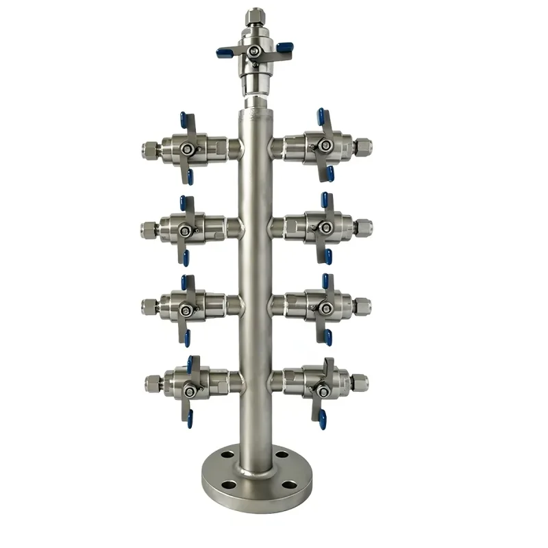
An instrument air header looks simple: one large tube, several branch valves and a drain. Yet many field problems begin with details that never reached the purchase order—simultaneous air demand, allowable pressure drop, valve access, condensate removal, or the thread standard at each outlet.
The header is the local distribution point between the plant air main and pneumatic users such as valve actuators, positioners and instruments. Its job is not only to split flow. It must isolate each user without shutting down the rest, avoid becoming a condensate trap, and remain serviceable after the surrounding cable trays and tubing are installed.
Start with the operating case, not the outlet count
Eight visible valves do not mean the header should be sized at eight times a nameplate flow. List each connected user and separate steady consumption from short-duration demand. A control valve actuator may consume little air while holding position but require a much larger burst during stroking. If several devices can move together during a trip, that credible simultaneous case should govern the header and upstream supply check.
Record the minimum pressure required at the worst user, the available pressure at the header inlet and the permitted pressure loss. The calculation route should include the supply line, header bore, branch valve, fittings, tube and user connection. A large header cannot correct an undersized upstream line or a restrictive branch valve.
| Design input | What it controls |
|---|---|
| Normal and peak air demand | Header bore and upstream supply capacity |
| Minimum user pressure | Allowable system pressure drop |
| Number of active and spare outlets | Body length, valve count and future capacity |
| Air quality and condensate | Drain position, material and cleaning |
| Ambient exposure | Corrosion resistance, handle and mounting design |
| Hazardous-area practices | Locking, tagging and project documentation |
Size the bore by peak demand and pressure loss
For a first pass, add the credible simultaneous branch flows and select a header bore that keeps velocity and pressure loss within the project limit. Compressible-flow behavior matters when pressure drops are significant, so the final check should use the actual inlet pressure, temperature, tube dimensions and fitting losses rather than a water-flow rule of thumb.
The first section after the inlet carries the full demand. Flow decreases after each takeoff, but the last user accumulates every upstream loss. Check at least the largest-demand branch and the most distant branch. If trip response time matters, include the volume and restriction of the downstream tubing as well.
Choose outlet count and spacing for maintenance
Provide only as many spare outlets as the expansion plan can justify. Every spare adds cost, another valve seat and another potential leak path. When spares are required, specify whether they are supplied with valves, plugs or caps and how they will be protected from contamination.
Outlet spacing should be based on the largest installed valve, tube fitting, wrench envelope and tag—not the branch boss diameter. Confirm that handles can complete their travel without contacting an adjacent fitting. Alternating outlets on opposite sides can shorten the assembly, but technicians still need a clear line of sight and room to connect tubing.
Valve selection is part of the header design
Quarter-turn ball valves give clear open/closed indication and low restriction. Needle valves provide more controlled opening but are not a substitute for a regulator. The project should define valve type, pressure-temperature rating, seat and seal material, handle style, locking requirement and flow direction.
Parker’s official distribution-manifold literature describes headers for distributing compressor air to pneumatic instruments and highlights lockable outlet valves, a drain, welded construction and pre-drilled mounting features. Those are useful design concepts, but their published rating belongs to Parker’s listed model—not automatically to a visually similar custom assembly. Review the Parker air header catalog when developing the specification.
Put the drain at the true low point
Instrument air systems can still carry condensate, compressor oil or debris. A drain installed on the drawing’s bottom may not be the low point after the header is mounted. Define the installed orientation, slope and drain accessibility. Vertical headers commonly use a bottom drain; horizontal arrangements need a deliberate low-point connection.
The drain valve and discharge method must suit the plant’s maintenance procedure. Do not place a drain where discharge can strike electrical equipment or personnel. If freezing is credible, include insulation, tracing or a protected location in the system design.
Material and construction
316 or 316L stainless steel is commonly considered for corrosive outdoor and process environments, while other grades may be suitable for controlled indoor service. Selection still depends on external chlorides, cleaning chemicals, temperature, connected materials and the site’s corrosion philosophy.
A welded body reduces the number of threaded joints, but weld quality becomes critical. Specify material traceability, weld procedure, internal cleanliness, surface treatment and examination appropriate to the service. Threaded branch connections must state the exact standard—NPT, BSPT or BSPP—and the sealing method. “Half-inch thread” is incomplete.
Mounting, testing and documentation
Mounting feet or brackets should carry the assembly without using connected tubing as structural support. Account for valve operating force, vibration, tube loads and thermal movement. Keep enough clearance to remove a valve or fitting without dismantling the entire header.
Define design pressure, maximum operating pressure and test pressure separately. State the test medium, duration, acceptance criterion and cleanliness/drying requirement. Pneumatic pressure testing stores substantial energy and requires a controlled procedure; do not substitute it casually for a specified hydrostatic or leak test.
What to put on the RFQ drawing
- service medium and air-quality requirement;
- normal and peak simultaneous demand;
- inlet pressure, minimum outlet pressure and temperature range;
- header bore, overall envelope and installed orientation;
- inlet, outlet and drain connection standards;
- outlet count, spacing, side and valve type;
- material grade, surface condition and traceability;
- mounting details, test scope and documentation.
The real AODSON instrument air header distribution manifold shown above is a configurable fabrication example. Outlet quantity, connection type, valves, body size and material can be produced to an approved drawing. Use the request form to send the operating case and dimensional sketch.
Frequently asked questions
Is a spare outlet always a good idea?
No. A justified spare can reduce future shutdown work, but unnecessary spares add valves and leak paths. Document how each spare is isolated and protected.
Can an air header be sized from inlet thread size?
No. The actual bore, simultaneous demand, pressure drop and upstream supply capacity determine performance.
Should the drain be automatic?
That depends on condensate load, maintenance philosophy and failure consequences. The important first step is a drainable geometry with an accessible low point.