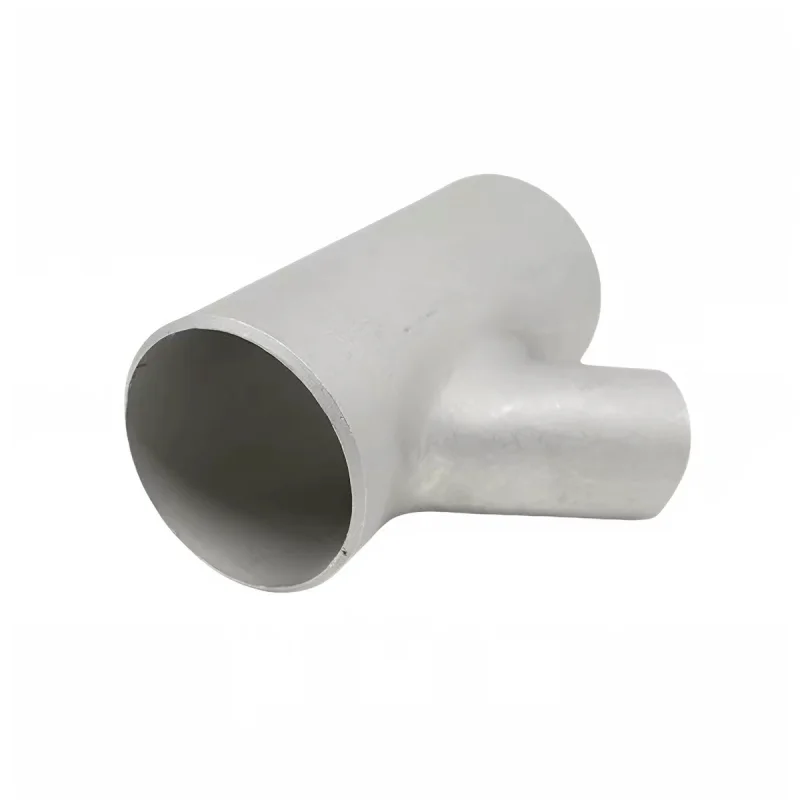
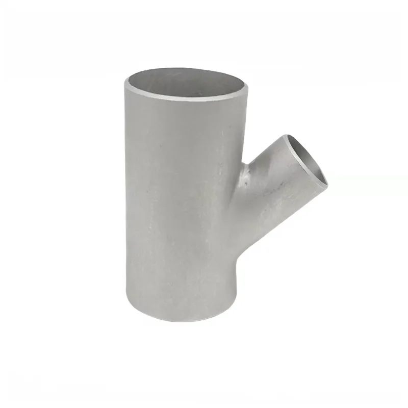
A straight tee turns branch flow through 90 degrees. A lateral tee usually sends it through an oblique angle, commonly 45 degrees. That difference can improve a piping route and sometimes reduce directional loss, but it does not make every lateral automatically more efficient or code-compliant.
The choice should consider flow direction, available space, branch loading, fabrication route, cleanability and the dimensional standard used for procurement.
Geometry changes the piping layout
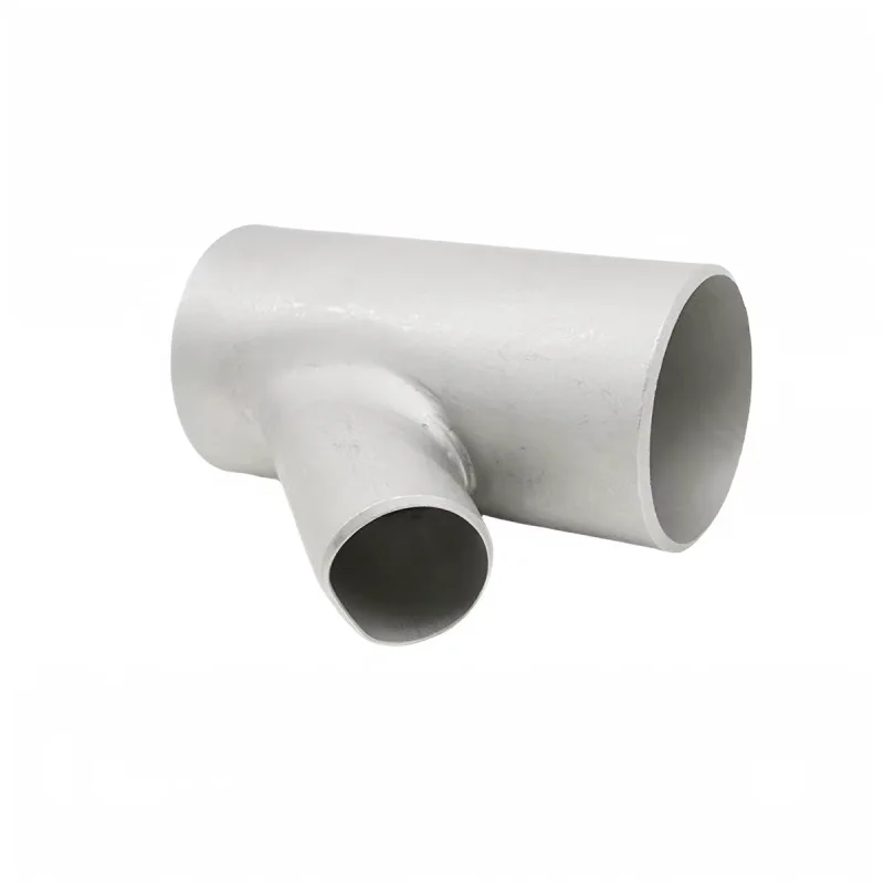
A straight tee is compact along the run but projects the branch perpendicular to it. A lateral tee carries the branch forward or backward, which can eliminate a downstream elbow when the destination is already diagonal. The lateral may therefore reduce total fittings and welds even if its own envelope is longer.
Mark the branch angle and orientation on the isometric drawing. “Left” and “right” are unreliable without a flow arrow or coordinate datum. For fabricated laterals, specify center-to-end dimensions rather than assuming a standard tee table applies.
Flow and pressure loss
Pressure loss depends on whether flow divides, combines or passes through the run, as well as area ratio, radius, angle and Reynolds number. An angled branch can make the change in momentum less abrupt in one direction, but a sharp intersection, unequal bore or internal weld intrusion can erase that advantage.
Use loss coefficients or a validated model for the exact configuration. Do not assign a single K value to every “45-degree tee.” In critical service, compare the complete routes: one lateral versus a straight tee plus an elbow, including pipe length and reducers.
Flow splitting is not automatically equal
Neither tee style guarantees equal flow. Division depends on downstream resistance, static pressure, elevation, valve position and branch geometry. A symmetric tee with identical pipe sizes can still split unevenly when one branch is shorter or feeds a lower-pressure destination.
If a precise split matters, add balancing valves, orifices or flow controls and calculate the system. A tee is a junction, not a metering device.
Standard fitting or fabricated branch?
ASME B16.9 covers overall dimensions, tolerances, ratings, testing and markings for factory-made wrought butt-welding fittings from NPS 1/2 through NPS 48. The official ASME B16.9 scope is the correct starting point when that standard is specified.
Not every lateral geometry or custom branch is a standard B16.9 fitting. A fabricated connection may instead be designed under the applicable piping code using defined pipe material, branch opening, reinforcement and qualified welding. The purchase order should state which route applies; a product name alone does not establish compliance.
Branch reinforcement and wall thickness
Cutting a branch opening removes pressure-retaining area from the run. Depending on the code, size ratio, wall thickness and design conditions, reinforcement may come from excess wall, a reinforced fitting, an integrally formed outlet or an added pad. External appearance does not reveal whether the area requirement has been met.
Provide design pressure, temperature, corrosion allowance, pipe schedule, material and joint efficiency. For cyclic service, also consider stress concentration at the crotch and external loads from connected piping.
Fabrication details that affect performance
- Match the actual inside diameters when a smooth flow path is required.
- Control root penetration so weld metal does not obstruct the bore.
- Define branch angle tolerance and clocking orientation.
- Use a welding procedure and filler compatible with both components.
- Specify heat treatment, pickling/passivation and NDE when applicable.
- Check accessibility for welding and inspection around the acute side of the branch.
For slurry, sanitary or drainable systems, the internal contour and orientation may matter more than a small theoretical pressure-loss difference. A pocket at the acute intersection can retain product or cleaning fluid.
External loads and supports
A lateral can change the direction and lever arm of branch loads. Include sustained weight, thermal expansion, vibration and occasional loads in the piping analysis. Avoid using the fitting as the nearest convenient support point unless the design allows it.
When a lateral replaces a tee-and-elbow combination, recalculate flexibility. Fewer welds do not necessarily mean lower nozzle load; the more direct route may be stiffer.
Selection table
| Condition | Often favors | Reason to verify |
|---|---|---|
| Branch destination is perpendicular | Straight tee | Simple layout and standard dimensions |
| Branch continues diagonally | Lateral tee | May remove an elbow and weld |
| Tight run length | Straight tee | Lateral can require more axial envelope |
| Lower-loss route sought | Compare complete systems | Internal contour and downstream fittings govern |
| Code pressure service | Qualified standard/design | Name and appearance do not prove compliance |
RFQ checklist
- run and branch nominal sizes plus actual schedules;
- branch angle, orientation and center-to-end dimensions;
- material grade and product specification;
- design pressure, temperature and corrosion allowance;
- applicable piping code and fitting standard;
- weld ends, internal contour and surface treatment;
- NDE, pressure test, markings and documentation;
- quantity and dimensional drawing.
See the real AODSON stainless steel lateral tee fittings for fabricated examples in multiple sizes. Final dimensions, wall thickness and inspection follow the approved specification. Send an isometric or marked sketch through the request form.