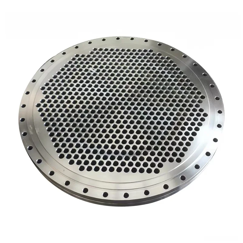
A heat exchanger tube sheet is more than a plate with repeated holes. It locates and supports the tubes, provides the interface for each tube-to-tube-sheet joint, and forms part of the boundary between process sides. A small drawing omission can affect tube insertion, joint integrity, inspection access or the final exchanger assembly. Buyers should therefore order the machined component against an approved exchanger design rather than a hole count alone.
This guide focuses on manufacturing and procurement of the stainless steel tube sheets shown in AODSON’s product range. The responsible exchanger designer must establish the applicable code, pressure conditions and acceptance criteria for the complete equipment.
Start with the exchanger drawing and design basis
Before machining begins, the buyer should provide the exchanger type, service fluids, design pressure and temperature, corrosion allowance where applicable, and the governing drawing revision. The required code or project specification must be stated explicitly. ASME’s published explanation of Section VIII Part UHX addresses tube sheet design for relevant shell-and-tube exchanger configurations; it is not a substitute for an approved calculation or a blanket certification of a purchased plate.
Define the complete hole pattern
A tube-hole layout needs a datum system, tube count, hole diameter and tolerance, center-to-center pitch, pattern orientation and coordinates for every omitted or special hole. Define the peripheral bolt circle separately from the tube pattern. The remaining material between adjacent holes is often called the ligament; its minimum value and the edge distances must be checked by the exchanger designer for the selected pattern and loading. A photo or a generic drilling template cannot establish those limits.
Include the side from which each feature is measured. Be explicit about face orientation, tube projection, spotfaces, grooves, recesses, pass-partition locations and any tube-free lanes. These details make the drawing usable for CNC programming and inspection without relying on verbal interpretation.
Select the tube-to-tube-sheet joint before finalizing holes
Tube expansion, welding, or a specified combination of the two can require different hole finishes, geometry, preparation and inspection. The joint choice depends on the tube and sheet materials, leakage requirements, thermal cycling, pressure differential and corrosive environment. For example, Alleima notes that higher-strength duplex tubing needs greater force during expansion than common austenitic tubing, and its SAF 2507 guidance recommends welding tube-to-tube-sheet joints in high-chloride service to reduce crevice-corrosion risk. That is material-specific guidance, not a universal instruction for every exchanger.
Agree the actual joint procedure with the exchanger manufacturer. A tube sheet supplier should not invent a hole tolerance or surface finish based only on a requested tube outside diameter.
| Drawing item | Why it matters | Typical verification |
|---|---|---|
| Plate material and heat identification | Connects the machined part to the approved design and corrosion assessment | Material certificate and traceability record |
| Thickness, flatness and datum faces | Controls stack-up, gasket seating and machining reference | Dimensional inspection against the drawing |
| Tube-hole diameter, position and pitch | Controls tube fit and the approved layout | Sampling plan, gauges or coordinate measurement as specified |
| Bolt circle and peripheral features | Controls assembly to the shell or channel | Position and diameter checks |
| Hole finish and edge condition | Affects insertion and the chosen joint procedure | Visual and specified surface checks |
| Required examinations | Defines acceptance beyond dimensions | Project-specified NDE, leak or pressure records where applicable |
Plan the machining and inspection sequence
Large patterns benefit from a stable datum strategy and controlled drilling or boring sequence. Allow for tool wear, chip removal and burr control, especially where hundreds of holes must retain consistent size and position. Inspect the gasket face and bolt features after final machining, and protect the finished surfaces during handling and export packing. The inspection plan should distinguish critical features from routine dimensions and state the sampling or full-inspection requirement before production.
Material selection also belongs to the service analysis. A 304, 316 or duplex label alone cannot demonstrate suitability for a chloride-containing process, a given temperature or a particular tube material. Record the exact grade, product form and certification required by the approved design; review tube and sheet compatibility, corrosion exposure and fabrication procedure together.
What to send with a tube sheet RFQ
- Approved 2D drawing and, where available, a 3D model with revision control;
- exchanger type, code or project specification, and design conditions;
- plate grade, thickness, diameter, heat traceability and certificate requirement;
- tube size, pattern, datum, tube-hole tolerance and intended joint method;
- gasket face, bolt circle, grooves, special holes and surface requirements;
- inspection, NDE, packaging, quantity and delivery requirements.
Use AODSON’s RFQ form to submit the approved drawing and acceptance plan. AODSON’s CNC machining capability and quality-control overview provide context for the manufacturing review.
Frequently asked questions
Can a tube sheet be quoted from tube count and outside diameter?
Only as a rough feasibility discussion. A production quotation needs the complete hole pattern, plate geometry, material, joint method and inspection requirements.
Is expansion always sufficient for a leak-tight joint?
No universal answer applies. The selected joint must follow the exchanger design, service conditions, applicable specification and approved procedure.
Does a machined tube sheet prove the exchanger meets a pressure code?
No. Code compliance concerns the designed and assembled equipment, its material records, fabrication and required examinations.
Technical references
ASME’s description of tube sheet criteria under Section VIII Part UHX identifies the exchanger design scope. Alleima’s SAF 2507 material data discusses tube expansion and high-chloride joint considerations for that particular alloy. Neither source defines the acceptance criteria for an unspecified AODSON component.