



Bridge Pull Handles for Equipment Doors and Panels
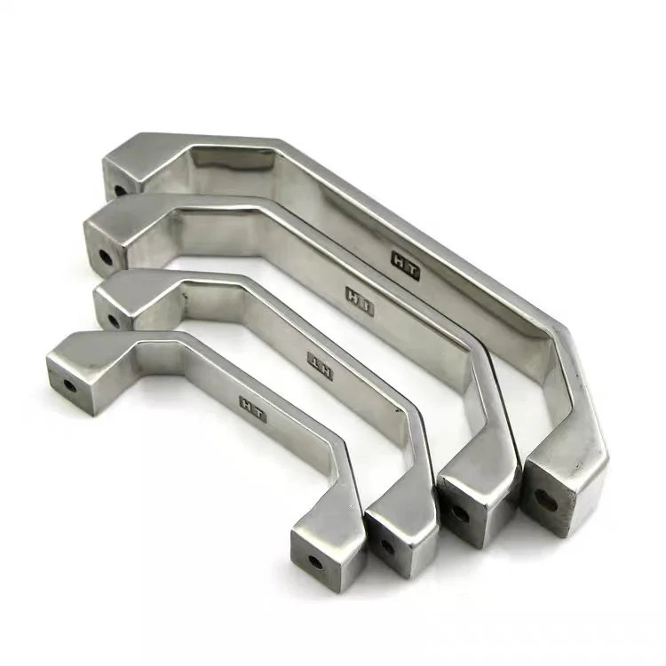
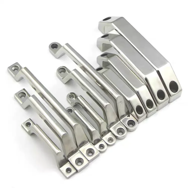
These stainless steel pull handles mount above the panel surface, leaving space beneath the grip for manual opening. The photographs show broad, angular bridge grips alongside narrower curved profiles. Choose the profile and mounting pattern to suit the panel layout, available hand clearance and required opening force.
Product Specifications
| Item | Reference configuration |
|---|---|
| Product type | Fixed, surface-mount bridge pull handle |
| Material | Stainless steel; supplier reference identifies 304. Confirm the specified grade and any material-document requirements before ordering. |
| Mounting-hole centres | 100, 120, 150 and 180 mm shown in the supplied dimension reference. These are centre-to-centre distances, not overall handle lengths. |
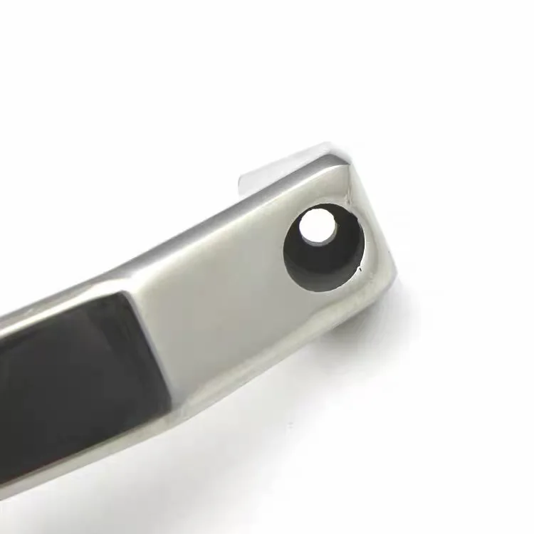
| Mounting interface | Two mounting feet with recessed holes. Hole diameter, recess geometry and fastener compatibility require a dimensioned drawing. |
| Grip profile | Broad angular and narrower curved styles shown; specify the selected style in the enquiry. |
| Surface appearance | Silver metallic finish as photographed. Agree the required polish and cosmetic acceptance sample with the quotation. |
| Dimensions to confirm | Overall length, grip width, projection, usable hand clearance, mounting-foot size and panel thickness |
| Load rating and accessories | No rated load or included mounting fasteners established by the supplied reference; confirm separately. |
Select the Mounting Pattern Before Ordering
For replacement handles, measure the distance between existing hole centres and check the space around each mounting foot. A matching hole pitch alone does not establish interchangeability: handle projection, screw-head clearance and access to the rear of the panel also matter.
- Hand clearance: Allow for the intended grip and any gloves used by the operator.
- Panel installation: Specify panel material, thickness, fixing arrangement and available fastener engagement.
- Opening force: State the expected pull direction and operating force so the handle and attachment can be reviewed together.
Typical Applications
Potential applications include machinery covers, electrical or general equipment enclosures, cabinet doors and removable access panels, subject to confirming the installation requirements. These handles are not presented as certified lifting points or safety grab rails.
Inspection and Project Requirements
Define inspection points on the approved drawing: hole pitch, mounting-face alignment, grip projection, edge condition and surface appearance. If material records, pull testing or other acceptance documents are required, include them in the enquiry for feasibility and quotation review; their availability is not assumed.
For a non-standard profile or mounting pattern, send a drawing for manufacturing review. Any change in material, dimensions, finish or marking must be agreed before production. See our quality-control capabilities for broader project inspection information.
Frequently Asked Questions
Are 100–180 mm dimensions the overall lengths?
No. The supplied reference labels 100, 120, 150 and 180 mm as mounting-hole centre distances. Request the corresponding drawing for overall dimensions.
Which screws fit these handles?
The mounting recess is visible, but screw size and head geometry are not confirmed. Match the screw to the approved hole dimensions, panel thickness and fixing arrangement; do not select it from the photograph alone.
Can these handles be used to lift equipment?
No lifting capacity is established here. If the application involves carrying or lifting, provide the load case and required verification before selection.
Request a Handle Quotation
Send the selected profile or marked photograph, hole-centre distance, full dimensions or drawing, material grade, finish, panel details, quantity and delivery destination. Include any inspection or load-test requirements so the quotation covers the intended assembly.
Send your handle drawing and request a quote · Browse machine handles and knobs